S’ouvre dans un nouvel onglet

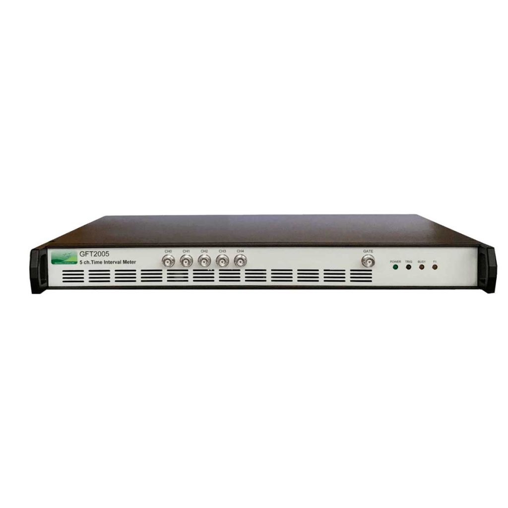
GFT2005

  • Five Channel Time Interval Meter: one Start and four Stops

    It has five channels: Channel 0 is used as the “Start” time reference for channels 1-4 being “Stops” events of the Time Interval measurement.

  • 10 MHz sample rate per channel

    The instrument uses an internal 10 MHz oscillator or an external very stable 10 MHz source.

  • 100 /1000 Mbit/s Ethernet interface

Request a quote

Applications

  • Time of flight mass spectrometry
  • Lab / R&D Characterizations
  • Fluorescent decay
  • Real time, time stamping
  • ATE (Automatic Test Equipment)
  • Optical and magnetic disk timing
  • Component Test
  • Variation in Pulse Timing
GFT2005

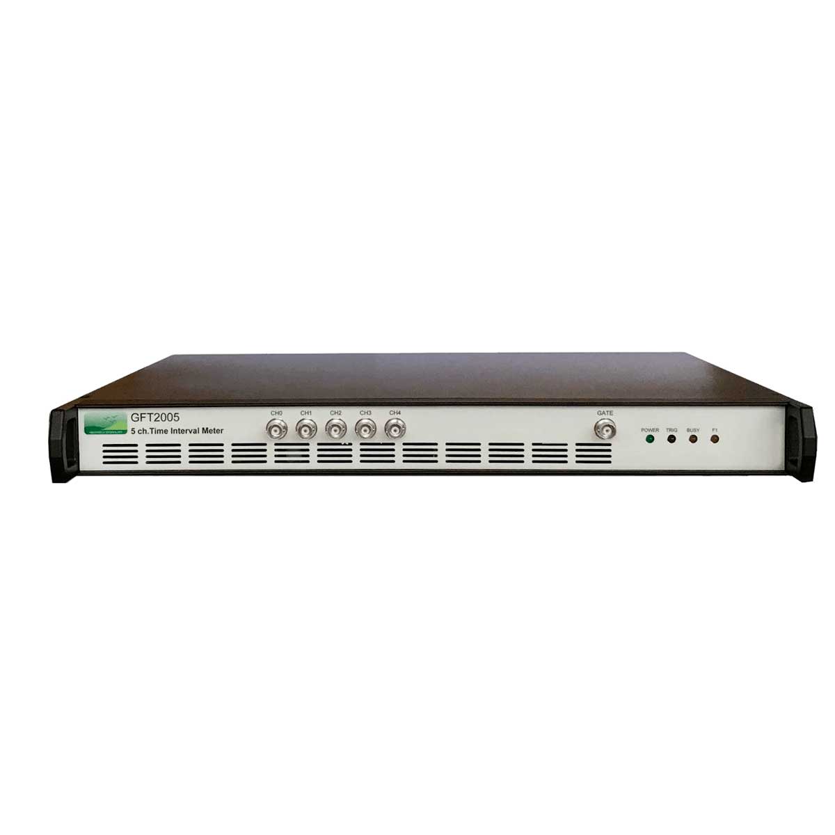
The GFT2005 is a very precise Time Interval Meter. It has five channels: Channel 0 is used as the “Start” time reference for channels 1-4 being “Stops” events of the Time Interval measurement. Each channel can measure the time of the rising edge of one electrical input, to 13 picosecond resolution with > 100 second range. Time Interval samples can be automatically processed to provide Mean, Max, Min and RMS/Jitter.

The instrument uses an internal 10 MHz oscillator or an external very stable 10 MHz source.

The Instrument offers 4 GPIO (digital bi-directional signals) under software control for communication to external equipment.

The GFT2005 is a low profile 19″, 1U rack instrument with Ethernet interface.

The instrument as a built in Web server that provide an easy remote control via a standard Web Browser. “Control panel Web page” from embedded web server provide an easy method to:

  • Configure settings for each channel and Control operation and status of the instrument
  • View the measurements (value and graphic form)
  • Save the measurement in your file computer.

Key features

  • Channel number5

TIM channel

  • Number1 Start, 4 Stops
  • Time resolution13 picoseconds
  • Time range>100 seconds
  • Time JitterLower than 50 ps RMS for Time intervals below 1 ms

Channel Input

  • Edge triggerRising
  • Input impedance50 Ω
  • Input couplingDC
  • ThresholdProgrammable from -2.5 to +2.5 Volts
  • Max safe input± 3.3 Volts

Gate Input

  • Level2 Volts minimum, active high
  • Input impedance50 Ω

Clock Reference

  • Internal10 MHz, available as TTL output
  • External10 MHz ± 10 PPM reference, 1 Volt p-p min

Measurement

  • Measurement trigger modeSingle or Repetitive (repeat count and repeat period are adjustable)
  • Sample per measurement1 to 1000
  • Sample rateUp to 10 MHz
  • Measurement type
    Mean, Max, Min, RMS/jitter of samples
    Graphic form of samples Mean
    File of sample and mean measurement

GPIO

  • Number of GPIO signals4 (digital bi-directional signal)
  • Signal level input2.0 V High min, 0.8 V Low max
  • Signal level Output2.4 V High min, 0.6 V Low max at 24 mA

General

  • Control interface10 / 100 / 1000 Mb/s Ethernet
  • SoftwareSet of Ethernet commands, Web page for Internet explorer, Chrome, Firefox
  • PowerLower than 20 W, 90-240 V / 50-60 Hz
  • IndicatorsPower, Trigger, Busy
  • ConnectorsChannel 0 to 4, Gate, Clock : BNC, Ethernet: RJ45
  • Dimension / Weight19", 1U, 400 mm (overall dimension) / Under 5 kg
  • Packaging2 handles in front and rear panel
  • Download data sheet

    Lorem ipsum dolor sit amet, consectetur adipiscing viverra ornare, eros dolor nulla.
    Download file
  • Lorem ipsum

    Lorem ipsum dolor sit amet, consectetur adipiscing viverra ornare, eros dolor nulla.
    Learn more