S’ouvre dans un nouvel onglet

Timing and synchronization, from a single trigger to an entire facility.

Greenfield instruments run inside laser fusion facilities, particle accelerators, quantum testbeds, pump-probe benches, plasma diagnostics and defense test programs. Each one has its own jitter budget, its own channel count and its own control system.
Requirements

Same picosecond. Six different problems.

A two-channel pump-probe bench and a 200-channel facility backbone are both called “picosecond timing”, and almost nothing else about them is the same. Four numbers decide the architecture: the jitter you can tolerate, how many channels have to fire, how far the trigger has to travel, and which control system owns it.
Architecture

One reference.
Many zones.

Across all six applications the topology is the same, and only the scale changes: one time base, optical distribution towards each zone, and the final picoseconds added locally — next to the instrument that needs them.
Application 01

Laser fusion and high-energy laser synchronization

In an inertial confinement facility, hundreds of beamlines have to converge on a target within a few picoseconds — and keep doing it for fifteen years, not for one campaign.
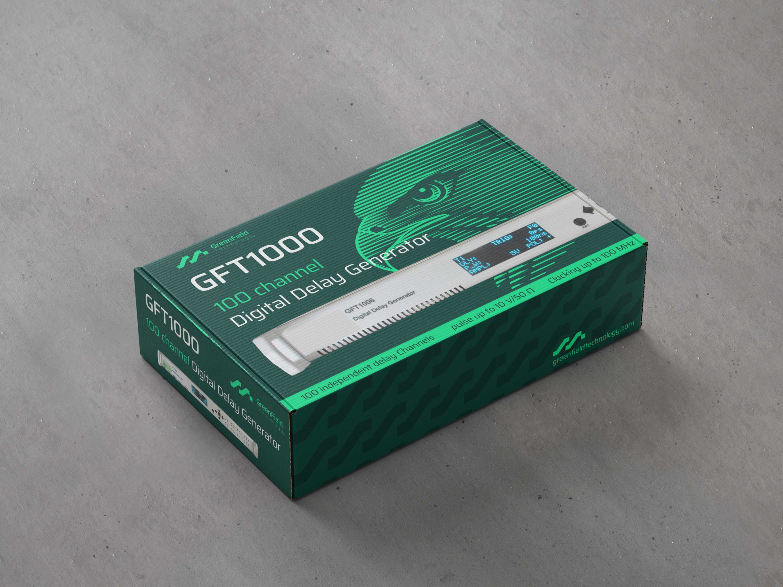
A GFT1000 timing master holds the facility time base; optical distribution carries it to each amplifier bay; GFT1008 units add the last picoseconds locally, in 1 ps steps, at 10 V into 50 Ω. Every channel reports its own state back to the control room, so a beam that arrives late becomes a diagnosable event instead of a mystery.

< 5 ps rms facility-wide
100 – 200+ channels
1 ps steps
24/7 multi-decade service

  • ▎ Instruments involved

    Picosecond Timing System GFT1000 → Pulse & Delay Generator GFT1008 → Pulse Shaping Modules GFT3022 →

  • Application 02

    Particle accelerator timing and trigger distribution

    Accelerators, synchrotrons and free-electron lasers need a trigger tree locked to the machine’s own RF reference, distributed over hundreds of metres of tunnel.
    Our timing units lock to an external reference up to 100 MHz and fan out optically, and every channel is addressable from EPICS, Tango, Python or LabVIEW — so machine events and beam data share one time base instead of two. Diagnostics sit on the same tree: screens, GFT1604 / GFT1804 digitizers, streak cameras and time-interval meters are gated from the reference that fired the machine, which is the only way a shot-to-shot comparison means anything.

    ≤ 100 MHz external clock 8 – 100 channels Optical site distribution EPICS · Tango native

    ▎ Instruments involved

    Picosecond Timing System GFT1000 · GFT9000 →
    High-Speed Digitizer GFT1604 · GFT1804 →

    Application 03

    Quantum timing: clock, trigger and gate control

    Quantum platforms are timing-limited before they are anything else. Gate sequences, detector gating windows and coincidence measurements all inherit the jitter of whatever generated them.
    For quantum testbeds we work at the fine end of the range: few-channel units, 1 ps stepping, low-noise outputs and stability across runs that last hours rather than shots. Sequences are programmed rather than patched — and when a setup graduates from optical table to rack, the programming model follows it unchanged.

    1 ps resolution
    < 5 ps rms jitter
    4 – 16 channels, bench or rack

  • ▎ Instruments involved

    Pulse & Delay Generator → Time & Frequency Meter →

    Applications 04 - 05 - 06

    Three more places where picoseconds decide the result.

    Smaller footprints, same physics. These setups usually start with two channels and a question about jitter — and often end up as a rack a whole team depends on.
  • 04 / Ultrafast optics

    Pump-probe timing and ultrafast delay control

    Pump-probe experiments live and die on the delay between two pulses. A digital delay generator covers the coarse range a mechanical stage would need metres of travel for, holds 1 ps steps across the whole scan, and keeps jitter low enough that the delay you program is the delay you measure. Two to eight channels is usually the whole requirement: one pump, one probe, a couple of diagnostics.

    1 ps steps 2 – 8 channels 10 V into 50 Ω

    Pulse & Delay Generator

  • 05 / Diagnostics

    Plasma diagnostics triggering and streak camera synchronization

    A plasma shot gives you one attempt. Streak cameras, framing cameras, X-ray diagnostics and fast scopes each need their own trigger, at their own amplitude, at their own moment — and the pulse has to stay clean in a violently noisy environment. Our delay generators drive 10 V into 50 Ω directly; pulse shaping modules handle the amplitude, width and edge conditioning each diagnostic actually wants.

    Single shot 8 – 32 channels Amplitude & width shaping

    Pulse Shaping Modules → High-Speed Digitizer →

  • 06 / Defense & aerospace

    Defense and aerospace test synchronization

    Test ranges and defense programs ask a different question: not how low the jitter can go, but whether it will still be true in ten years, across a whole site, under audit. We have delivered synchronization systems on both sides of the Atlantic, with traceable calibration, documented architectures and long-term component support designed in from the start.

    Site-wide distribution Traceable calibration Long-term support

    Picosecond Timing System → Custom & OEM →

    Before the first quote

    Questions we get every week.

    The answers we would give you on the phone, in the order we usually give them.

      Work backwards from the measurement, not from the datasheet. If your detector integrates over 100 ps, a 5 ps system is already invisible in your error budget. If you are resolving a 10 ps feature, jitter has to sit an order of magnitude below it.

      Optically. Over long runs coax collects ground loops and drifts with temperature. An optical link carries the reference to each local node, and the final picoseconds are added there rather than at the source.

      Then it becomes the seventh. Custom development — from a component to a complete instrumented system — is how a large share of the current catalog started.

      A delay generator produces a handful of precisely delayed pulses from one trigger, on one bench. A timing system distributes a common time base across a whole installation, with delay generators sitting at its edges. Small experiments need the first; facilities need both.

      Yes — Ethernet (RJ45 & SFP), cPCI/PXI/PXIe, USB, RS232, GPIB and VXI/VME depending on the model, with EPICS, Tango, Python and LabVIEW on the software side. Full list on the technologies page.

      We do, directly. Calibration, verification and repair are handled in-house rather than subcontracted — conditions on the services page.

    Tell us what the instrument has to do. We'll tell you how.

    Calibration, repair, upgrade or a custom development: describe it in a few lines and an engineer answers within two working days — with a real technical response, not an acknowledgement of receipt.
    Request a quote