S’ouvre dans un nouvel onglet

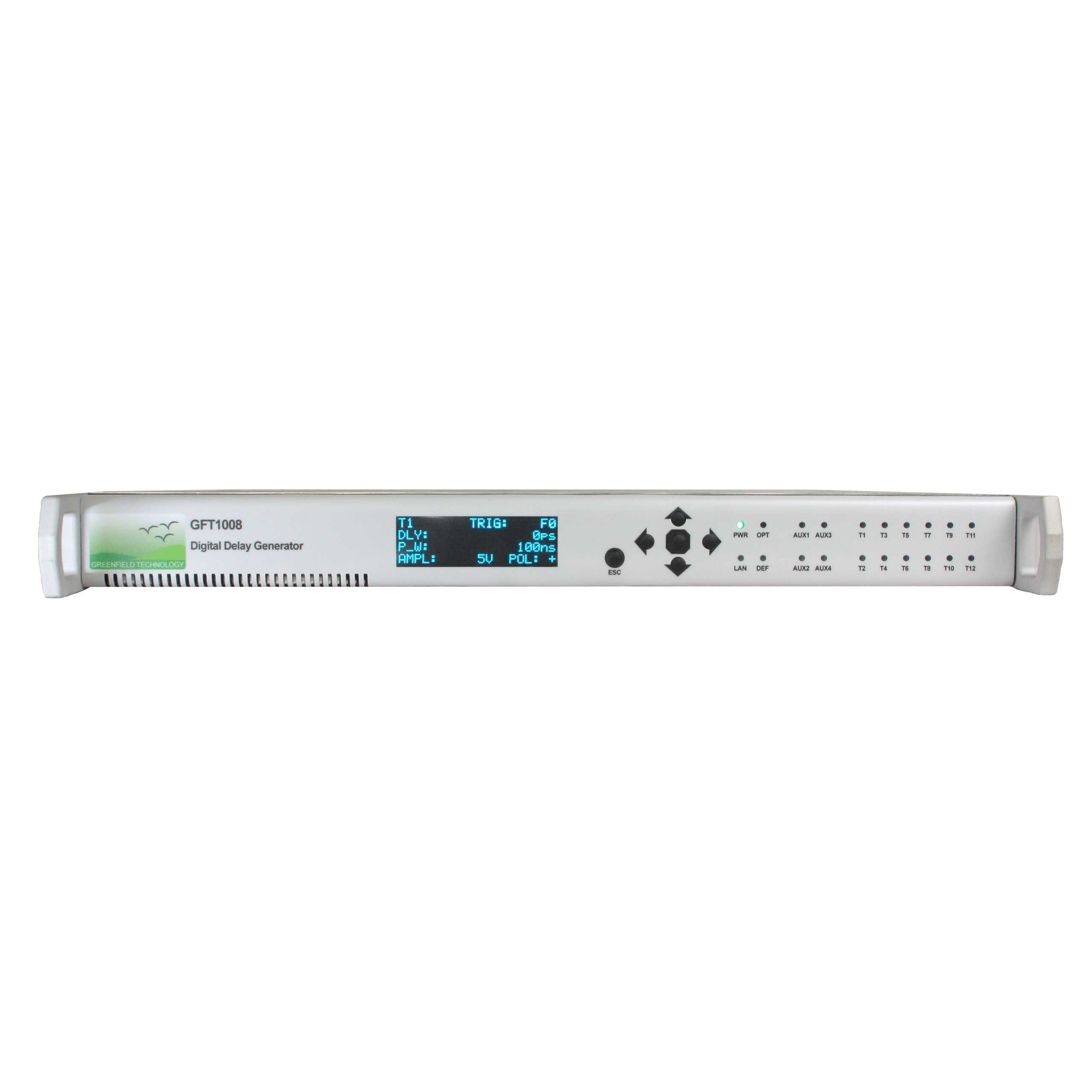
GFT1008

Channel Digital Delay Generator

  • 8/12/16 Independent Delay Channels 

  • Independent trigger rates for each channel

    One input channel, or two internal synchronized timers are used to trigger all output channels

  • Adjustable output pulse up to 10 V

    BNC outputs deliver up to 10 V, 1.5 ns under 50 Ω. Pulse amplitude and width are adjustable on each output channel.

Applications

  • 8 Independent Delay Channels (or 4/12/16 in option)
    • <1 ps delay resolution
    • <10 ps jitter for internal triggered delays
    • Up to 10 second range
  • Adjustable output pulse up to 10 V
  • Independent trigger rates for each channel
  • Controlled via Ethernet /Internet (web page) and front panel
  • Compact packaging: Rack 19″, 1U
  • Options:
    • Extension to 12 or 16 channels
    • Electrical channel output (Amplitude): 1.5 to 5V, 15 to 50V, 3V with fast rise time,
    • Optical channel output

The GTF1008 Digital Delay Generator provides eight independently delayed pulses on the rear panel with options for four, twelve or sixteen channels. Delays up to 10 seconds can be programmed with 1 ps resolution, and channel-to-channel jitter is less than 10 ps RMS. BNC outputs deliver up to 10 V, 1.5 ns under 50 Ω. Pulse amplitude and width are adjustable on each output channel.

One input channel, or two internal synchronized timers are used to trigger all output channels. One T0 channel is used as a time reference for all the delayed output pulses.

The GFT1008 is a Digital Delay Generator that operates either as a standalone device, or as a component in a timing system (Option 2). In a timing system, the GFT1008 is operated in conjunction with a Master Transmitter that controls and synchronizes a number of GFT1008 DDGs via optical fibers.

GFT1008 parameters can be locally controlled over the front panel keys and LCD display, and remotely controlled via Ethernet (1 Gb/s) or Internet (web page from internal web server).

Key features

  • Delay resolution1 ps

Delay Channel

  • Number 8 independents
  • AccuracyLower than 100 ps + delay (s) x 10-7
  • Time Base160.00 MHz frequency, ±25 ppm stability

External Trigger Input

  • Repetition RateUp to 1 MHz or single-shot
  • Trigger Level± 3.3 V / 50 Ω, step of 1 mV / Maximum ± 5 V during 1 µs
  • SlopePositive
  • Minimum Trigger DelayLower than 100 ns (insertion delay)

Internal Trigger

  • Two Synchronized TimersFrequency = 1 Hz to 1 MHz, resolution = 6.25 ns

Output Pulse T1 to T8

  • Amplitude3 V to 10 V in steps of 10 mV
  • Load50 Ω
  • Rise/Fall TimeLower to 1.5 ns / 1.5 ns @ 10 V
  • Width50 ns to 10 ms in steps of 6.25 ns ± 3.125 ns

External Time Reference

  • Threshold0 V, internal 50 Ω
  • LevelMin -3 dBm, typical 0 dBm
  • Frequency10 MHz (other frequencies are available up to 100 MHz)

General

  • User InterfaceFront panel, Ethernet 1 Gb/s, Internet (web page) – RJ45
  • Power Consumption90 to 240 V / 50 – 60 Hz/ 30 W
  • Weight / SizeLower than 6 kg / 19” W X 410 mm D X 1U H

Options

  • 1
    -04C/08C/12C/16C : 4/8/12/16 channels
  • 2
    -OTS/OTB: Optical input for timing System mode (SC/APC) / Bidirectional link (LC/PC). 1550 nm, jitter < 15 ps rms + delay x 10-8 (channel-to-channel in internal trigger), single or repetitive trigger
  • 3Configurable by group of 4 channels
    -STD: base version
    -3.3V: (Bank of 4 channels) 3.3 V channel output, rise/fall time = 1/1 ns (700 ps typ.) into 50 Ω. Width = 50 ns to 10 s, in step of 6.25 ns; polarity: positive or negative, RMS jitter< 6 ps + delay x 10-8
    -05V: (Bank of 4 channels) 1.5 V to 5 V channel output, step of 1 mV, rise/fall time = 1/1 ns into 50 Ω @ 5 V, 3/3 ns into 50 Ω @ 1.5 V; 3 V to 10 V channel output, step of 2 mV, rise/fall time = 2/2 ns into >1 kΩ. Width = 50 ns to 10 s, in step of 6.25 ns; polarity: positive or negative
    -50V: (Bank of 4 channels) 15 V to 50 V channel output, width = 50 ns to 5 µs, rise/fall time = 3/15 ns into 50 Ω
    -W850ST/W1310SC/W1310FC/W1550SC/W1550FC: (Bank of 4 channels) optical channel output >250 µW, width = 0.1 to 10 µs, rise/fall time = 1/2 ns; RMS jitter< 10 ps + delay x 10-8, wavelength 850 nm (ST), 1310 nm (SC or FC), 1550 nm (SC or FC)
  • 4
    -AUX: AUXILIARY INPUTS/OUTPUTS details (*not compatible with extension to 16 channels)
    -INH/GAT*: INHibition/GATe input, adjustable threshold
    -INH/GAT2*: INHibition/GATe input 2, adjustable threshold
    -CLK*: Clock output (sinus, AC, 2V pp, Time base / 2)
    -T0*: T0 output
  • 5
    -TB: Time base between 10 to 100 MHz (CLK IN) and 150 to 200 MHz (Timing system)
  • 6Limited performances
    -100: 100 ps delay channel resolution
    -2n: RMS jitter < 2 ns + delay x 10-8 (external trigger to any channel)
  • 7
    -SFPLX: Ethernet with SFP module – 770 nm to 860 nm, LC/PC
    -SFPSX: Ethernet with SFP module – 1270 to 1355 nm, LC/PC
  • Data sheet (PDF)

    Lorem ipsum dolor sit amet, consectetur adipiscing viverra ornare, eros dolor nulla.
    Download file
  • User manuel

    Lorem ipsum dolor sit amet, consectetur adipiscing viverra ornare, eros dolor nulla.
    Download file

Request a quote for GFT1008

Fill out the entire form to receive your quote